Published on July 29, 2025 by MakerWorks Team
Motors are the muscles of robotics and automation. This guide will teach you how to control various types of motors using your Arduino, including **DC motors**, **servo motors**, and **stepper motors**.
Types of Motors:
- **DC Motors:** Simple, continuous rotation. Ideal for applications where precise positioning isn't critical, like driving wheels. Requires a **motor driver** (e.g., L298N, L9110S) for speed and direction control as Arduino pins can't supply enough current directly.
- **Servo Motors:** Offer precise angular control, usually within a 0-180 degree range. Commonly used in robotics for specific movements, such as robot arms, steering mechanisms, or camera gimbals.
- **Stepper Motors:** Provide very precise step-by-step movement, making them perfect for applications requiring accurate positioning and repeatable motion, like 3D printers or CNC machines.
Controlling a DC Motor (Basic):
To control a DC motor's direction and speed, you'll typically use an H-bridge motor driver.
What You'll Need:
- Arduino board
- **L298N Motor Driver Module** (or similar H-bridge driver)
- **DC Motor** (e.g., a small 3-6V motor)
- External Power Supply (e.g., 9V battery pack or power adapter for the motor)
- Jumper wires
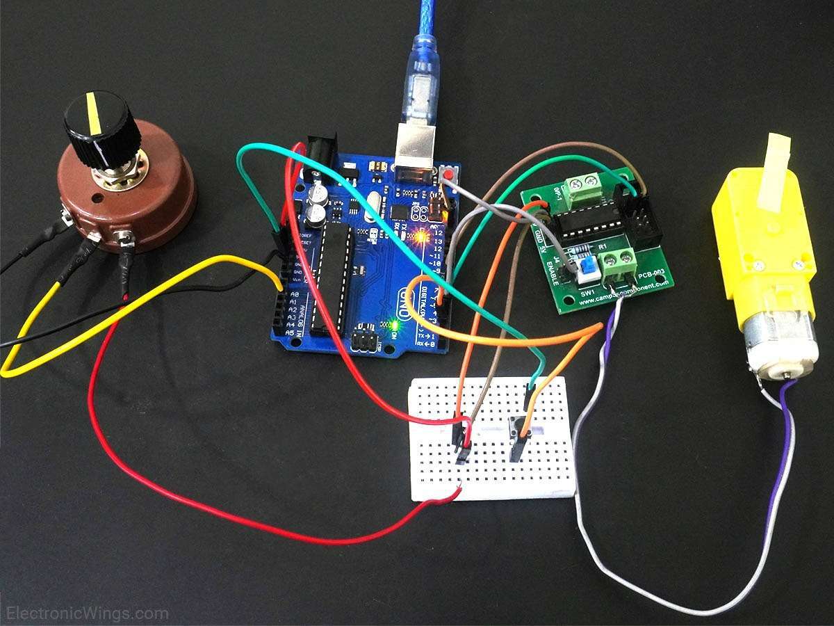
Circuit Diagram (DC Motor with L298N):
Connect your Arduino's digital pins to the IN pins of the L298N, and an Arduino PWM pin to the EN pin for speed control. Connect your motor to the OUT pins of the L298N, and provide external power to the driver.
 Basic wiring for a DC motor with an L298N driver.
Arduino Code (DC Motor Example):
// L298N Motor Driver Pin Definitions
const int enA = 9;  // Enable pin for Motor A (Connect to Arduino PWM pin)
const int in1 = 10; // Input 1 for Motor A
const int in2 = 11; // Input 2 for Motor A

void setup() {
  // Set all motor control pins as outputs
  pinMode(enA, OUTPUT);
  pinMode(in1, OUTPUT);
  pinMode(in2, OUTPUT);
}

void loop() {
  // Rotate motor in one direction (e.g., clockwise)
  digitalWrite(in1, HIGH);
  digitalWrite(in2, LOW);
  analogWrite(enA, 200); // Set speed to ~78% of max (0-255)
  delay(2000); // Run for 2 seconds

  // Stop the motor
  digitalWrite(in1, LOW);
  digitalWrite(in2, LOW);
  analogWrite(enA, 0); // Speed 0 = stop
  delay(1000); // Stop for 1 second

  // Rotate motor in the opposite direction (e.g., counter-clockwise)
  digitalWrite(in1, LOW);
  digitalWrite(in2, HIGH);
  analogWrite(enA, 200);
  delay(2000); // Run for 2 seconds

  // Stop the motor again
  digitalWrite(in1, LOW);
  digitalWrite(in2, LOW);
  analogWrite(enA, 0);
  delay(1000); // Stop for 1 second
}
Explanation:
- `analogWrite(enA, speed)`: Controls the motor speed using Pulse Width Modulation (PWM) on the enable pin. `0` is off, `255` is full speed.
- `digitalWrite(in1, HIGH/LOW)` and `digitalWrite(in2, HIGH/LOW)`: These control pins determine the direction of the motor's rotation.
Controlling a Servo Motor:
Servo motors are much simpler, requiring only one signal pin, power, and ground. The Arduino `Servo.h` library makes control very easy.
What You'll Need:
- Arduino board
- **Servo Motor** (e.g., SG90 mini servo)
- Jumper wires
Arduino Code (Servo Example):
#include <Servo.h> // Include the Servo library

Servo myServo;  // Create a servo object

void setup() {
  myServo.attach(9); // Attach the servo to digital pin 9
}

void loop() {
  myServo.write(0);   // Move servo to 0 degrees
  delay(1000);
  myServo.write(90);  // Move servo to 90 degrees
  delay(1000);
  myServo.write(180); // Move servo to 180 degrees
  delay(1000);
}
This is just a brief overview. Controlling different motors involves specific libraries and setup. Explore more details for stepper motors and advanced control techniques in dedicated tutorials!
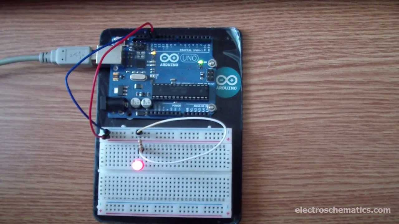
 Typical circuit for blinking an LED with Arduino.
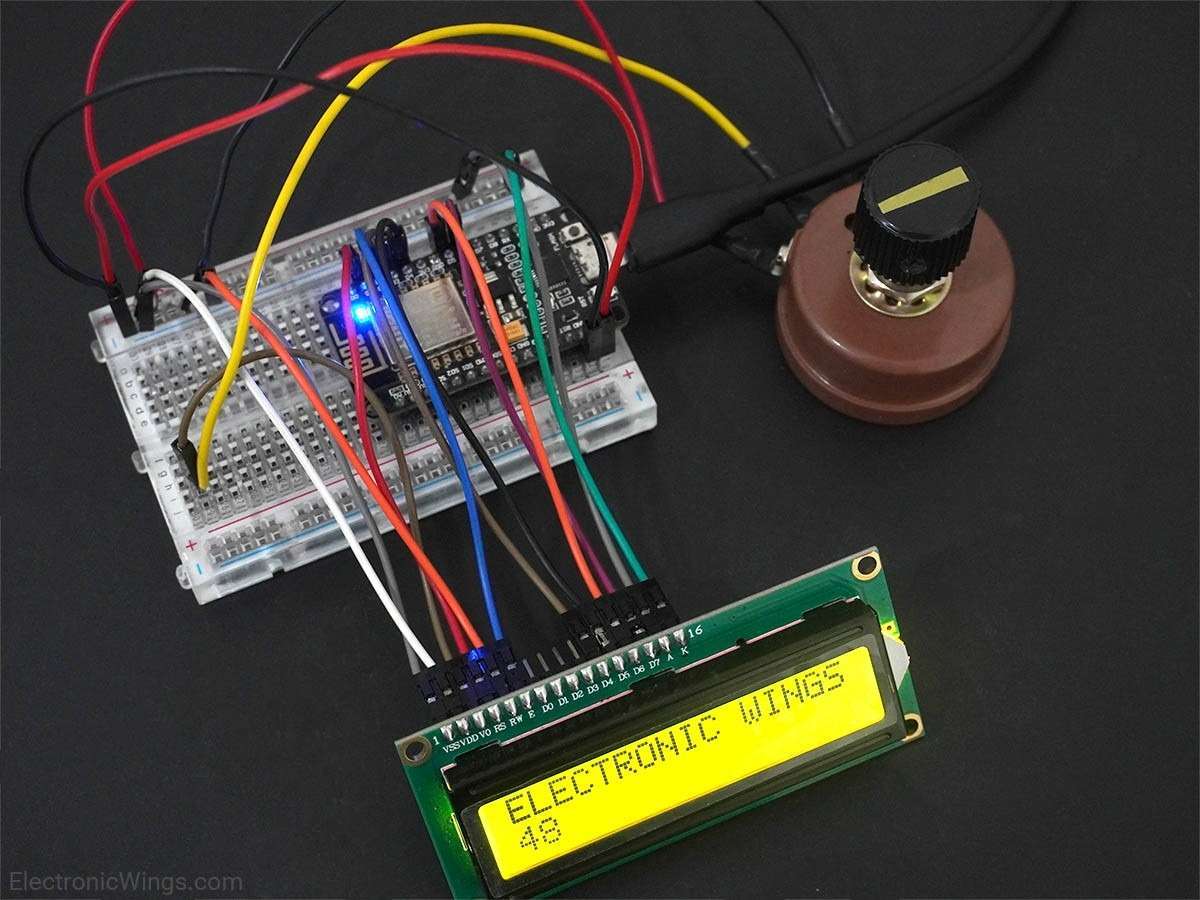
 Example of direct 16x2 LCD wiring (Note: detailed wiring diagram is complex and requires specific pin mappings).
 Simple wiring for a 16x2 LCD with an I2C module.
 Raspberry Pi Imager in action, simplifying OS installation.
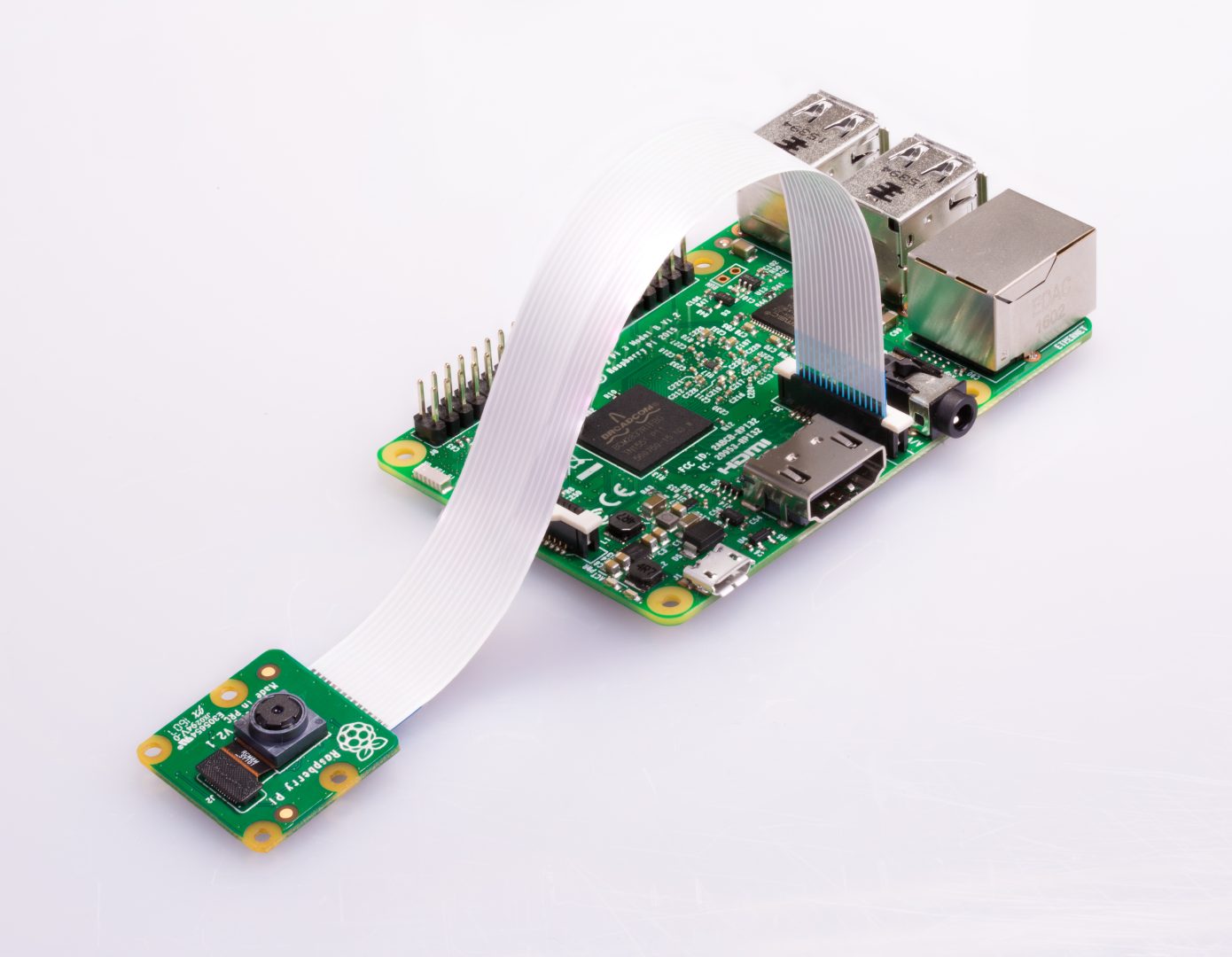
 Properly connecting the ribbon cable to the CSI port on your Raspberry Pi.
 Basic wiring for a DHT11 sensor to Raspberry Pi GPIO.
 A simple Node-RED flow for reading DHT11 data and displaying it.